Classes handling meshes
We propose here some classes able to manipulate meshes in 2-D and
3-D. Only conforming meshes are correctly treated in Montjoie, they
can comprise triangles and quadrilaterals in 2-D, tetrahedra, pyramids,
wedges (triangular prisms) and hexahedra in 3-D. Many operations can
be performed, e.g. reading/writing meshes in several formats,
creation of basic meshes (sphere, cube, cylinder, etc),
refinement of meshes (locally or globally). If you want to use only mesh
potentialities in Montjoie, you can include MontjoieMesh.hxx instead
of Montjoie.hxx and compile with Makefile.mesh. All the file formats use 1-convention,
that is to say that every number (vertex number, element number)
begins from 1. In the mesh structure proposed by Montjoie, the
0-convention is used, every number begins from 0. Therefore, in the
operations of reading/writing, a conversion is performed, so that it
is transparent for the user. But if you try to display the vertex
numbers of an element in your C++ code, and compare the numbers with
the graphical display given by Medit, the numbers will be shifted.
Declaration
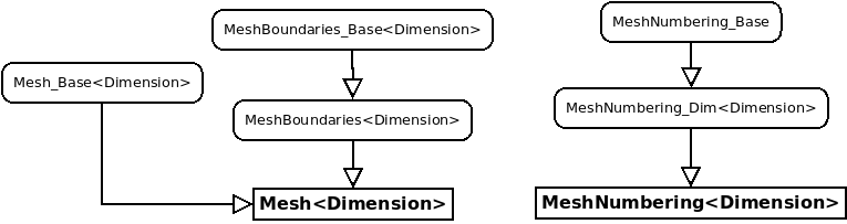
The leaf class Mesh depends on a template parameter that is the dimension. The class MeshNumbering stores numbers (usually associated with degrees of freedom) and relies on an existing mesh. Only these classes have to be used in the applications, the other classes are only intermediary classes :
// declaration of a mesh in 1-D
Mesh<Dimension1> mesh;

// declaration of a mesh in 2-D
Mesh<Dimension2> mesh;

// mesh numbering
MeshNumbering<Dimension2> mesh_num(mesh);

// declaration of a mesh in 3-D
Mesh<Dimension3> mesh;

// mesh numbering
MeshNumbering<Dimension3> mesh_num(mesh);
In the figure below, we display the hierarchy of intermediary classes used for the Mesh class (2-D and 3-D only).
The elementary entities (edge, face, volume) included in a mesh are represented by the following classes : Edge<Dimension>, Face<Dimension> and Volume. They are accessed through methods Boundary, BoundaryRef and Element :
#include "Mesh/MontjoieMesh.hxx"

using namespace Montjoie;

int main(int argc, char** argv)
{
  InitMontjoie(argc, argv);

  {
    Mesh<Dimension2> mesh;
    // you can read a mesh from a file
    mesh.Read("test.mesh");

    // Loop over vertices (R2)
    for (int i = 0; i < mesh.GetNbVertices(); i++)
        cout << "Vertex " << i << " = " << mesh.Vertex(i) << endl;

    // Loop over elements (Face<Dimension2>)
    for (int i = 0; i < mesh.GetNbElt(); i++)
        cout << "Face " << i << " = " << mesh.Element(i) << endl;

    // Loop over referenced edges (Edge<Dimension2>)
    for (int i = 0; i < mesh.GetNbBoundaryRef(); i++)
      cout << "Referenced edge " << i << " = " << mesh.BoundaryRef(i) << endl;
  }

  {
    Mesh<Dimension3> mesh;
    // you can read a mesh from a file
    mesh.Read("test.mesh");

    // Loop over vertices (R3)
    for (int i = 0; i < mesh.GetNbVertices(); i++)
        cout << "Vertex " << i << " = " << mesh.Vertex(i) << endl;

    // Loop over elements (Volume)
    for (int i = 0; i < mesh.GetNbElt(); i++)
       cout << "Element " << i << " = " << mesh.Element(i) << endl;

    // Loop over referenced faces (Face<Dimension3>)
    for (int i = 0; i < mesh.GetNbBoundaryRef(); i++)
cout << "Referenced face " << i << " = " << mesh.BoundaryRef(i) << endl;
  }

  return FinalizeMontjoie();
}
Referenced edges (faces in 3-D) are usually edges located on the boundary of the domain. In Gmsh, it corresponds to the boundaries created by using the keyword Physical Line (Physical Surface in 3-D). You can impose boundary conditions or specify a curve on these referenced edges.
Basic use of 2-D and 3-D meshes
A complete test of Mesh class is present in file
src/Program/Test/MeshTest.cc. Here we write a simple
code to create a basic 2-D mesh and 3-D mesh.
#include "Mesh/MontjoieMesh.hxx"

using namespace Montjoie;

int main(int argc, char** argv)
{
  InitMontjoie(argc, argv);

  // creation of a simple mesh in 2-D
  Mesh<Dimension2> mesh;

  // creation of vertices
  mesh.ReallocateVertices(4);
  mesh.Vertex(0) = R2(-1, -1);
  mesh.Vertex(1) = R2(1, -1);
  mesh.Vertex(2) = R2(1, 1);
  mesh.Vertex(3) = R2(-1, 1);

  // creation of elements (you provide vertex numbers for each element)
  mesh.ReallocateElements(2);
  int ref = 1;
  mesh.Element(0).InitTriangular(0, 1, 3, ref);
  mesh.Element(1).InitTriangular(1, 2, 3, ref);

  // and edges on the boundary (you provide extremities numbers)
  mesh.ReallocateBoundariesRef(4);
  mesh.BoundaryRef(0).Init(0, 1, ref);
  mesh.BoundaryRef(1).Init(1, 2, ref);
  mesh.BoundaryRef(2).Init(2, 3, ref);
  mesh.BoundaryRef(3).Init(3, 0, ref);

  // we create connectivity between edges and elements
  mesh.FindConnectivity();

  // creation of mesh in 3-D
  Mesh<Dimension3> mesh;

  // creation of vertices
  mesh.ReallocateVertices(5);
  mesh.Vertex(0) = R3(0, 0, 0);
  mesh.Vertex(1) = R3(1, 0, 0);
  mesh.Vertex(2) = R3(0, 1, 0);
  mesh.Vertex(3) = R3(0, 0, 1);
  mesh.Vertex(4) = R3(1, 1, 1);

  // creation of elements
  mesh.ReallocateElements(2);
  mesh.Element(0).InitTetrahedral(0, 1, 2, 3, ref);
  mesh.Element(1).InitTetrahedral(1, 2, 3, 4, ref);

  // creation of faces on the boundary
  mesh.ReallocateBoundariesRef(6);
  mesh.BoundaryRef(0).InitTriangular(0, 1, 2, ref);
  mesh.BoundaryRef(1).InitTriangular(0, 1, 3, ref);
  mesh.BoundaryRef(2).InitTriangular(0, 2, 3, ref);
  mesh.BoundaryRef(3).InitTriangular(4, 1, 2, ref);
  mesh.BoundaryRef(4).InitTriangular(4, 1, 3, ref);
  mesh.BoundaryRef(5).InitTriangular(4, 3, 2, ref);

  // we create connectivity between edges, faces and elements
  mesh.FindConnectivity();

  // you can also read a mesh (instead of creating it)
  // the extension tells what format is specified
  mesh.Read("file.mesh");

  // and write it (in any format)
  mesh.Write("file.msh");

  return FinalizeMontjoie();
}
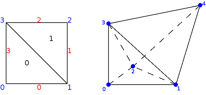
The 2-D and 3-D meshes we have created by typing the previous commands are displayed in the figure below
Basic use of 1-D meshes
A simple class has been created for 1-D meshes which is clearly different from the classes for 2-D and 3-D meshes. Below, we have written an example of use of this class
#include "Mesh/MontjoieMesh.hxx"

using namespace Montjoie;

int main(int argv, char** argv)
{
InitMontjoie(argc, argv);
Mesh<Dimension1> mesh;

// regular 1-D mesh
// for example, you want to mesh the interval [-3, 2] with 100 points
int ref_domain = 1; // reference for all the elements created
mesh.CreateRegularMesh(Real_wp(-3), Real_wp(2), 100, ref_domain);

// vertex i is accessible in mesh.Vertex(i)
cout << "Coordinate of vertex 4" << mesh.Vertex(4) << endl;

// element i is accessible in mesh.Element(i)
cout << "Element 4" << mesh.Element(4) << endl;

// you can write the mesh (only vertices are written)
mesh.Write("points.dat");

return FinalizeMontjoie();
}
Available formats and related mesh generators
Here we list all the formats handled by Montjoie, and mesh generators able to write meshes in that format. Conversion of mesh files can be achieved by using convert_mesh tool.
| Extension | Mesh generator used | Comments |
| .mesh/.meshb | Ghs3D (INRIA) | Use medit to display this format |
| .msh | Gmsh | |
| .gts | Gnu Triangulated Surface | Only 3-D triangular surfacic meshes |
| .stl | Stereolithography | Only 3-D triangular surfacic meshes |
| .exo | Cubit | able to produce second order curved mesh |
| .neu | Harpoon | Neutral Gambit Format |
| .mh2/.mh3 | Geompack | able to produce hybrid meshes in 2-D and 3-D |
| .vtk | Visualization Toolkit | Use Paraview to display this format |
| .mit | Onera format | |
| .vf | Onera format | |
| .obj | Wavefront geometry | Format readable by most of 3D softwares |
| .hmascii | Hypermesh | able to produce hybrid meshes |
| .dat | Castem | internal format of castem ? |
| .cas | Nastran | Nastran mesh (ascii only) |
| .neub | Neutral | mesh format used by MPS |
Convenients tools associated with meshes
First, we list the files contained in the directory src/Program/Mesh and that are associated with targets:
add_circular_layer.cc(make add_circle) : adds circular layers to an initial mesh of a circle, with automatic refinement.add_spherical_layer.cc(make add_sphere) : adds spherical layers to an initial mesh of a ball, with automatic refinement (hexahedral only).-
convert2mesh.cc(make convert) : conversion between mesh formats, the binary file is called convert_mesh.x. This binary is used by the script geo2mesh. -
manipule.cc(make manipule) : you can perform basic operations on 3-D meshes by using this tool (adding/removing a vertex, face, element, changing references, applying a translation/rotation, etc) -
manipule2D.cc(make manipule2D) : you can perform basic operations on 2-D meshes by using this tool (adding/removing a vertex, face, element, changing references, applying a translation/rotation, etc) -
periodize_mesh.cc(make per_mesh) : Generation of a mesh by periodizing an initial cell with respect to x and/or y and/or z, and/or theta. The name of the executable is per_mesh.x. Type ./per_mesh.x --help to have a detailed help. -
sym_mesh.cc(make sym_mesh) : symmetrizes a mesh with respect to x, y, and/or z. The name of the executable if sym_mesh.x. Type ./sym_mesh.x --help to have a detailed help.
We then list other files contained in the folder src/Program/Mesh.
- coherence.cc : removes unused vertices and boundaries in the mesh. An unused vertex/boundary doesn't belong to an element of a mesh (tri/quad in 2-D, tet/pyramid/prism/hex in 3-D).
- extract_boundary.cc : extraction of surface mesh from volume mesh
- geo2pack.cc/geo3pack.cc : interpretation of .geo files and use of Geompack to generate a 2-D or 3-D mesh based on informations provided in .geo files.
- locate_face.cc : extracts a single face from a mesh, and surrounding faces so that you can figure out where is a face in a mesh.
- reg_geo.cc : creates a regular mesh of a cube, and writes a .geo file so that each small cube is a transfinite volume.
How to add circular layers to an initial mesh of a circle
Concentric layers can be added by the code add_circular_layer.cc (in the folder src/Program/Mesh, compiled with the target add_circle) :
make add_circle
In order to add circular layers, you need to write a file raff.don that contains in the first column the radii to add. These radii have to be greater than the extern radius of the input mesh (for example disque.mesh). In the second column you specify the refinement to apply in θ. In the third column, you can write the reference associated with this radius. If this value is omitted, it is assumed that the circle is not referenced. The mesh final.mesh is obtained by executing the following command :
./add_circle.x disque.mesh final.mesh 3 raff.don
The parameter 3 given in this example is the reference of the extern circle (in disque.mesh). It depends on the input mesh you provide. You can download the example files disque.mesh and raff.don. Below, we show the result of this operation :
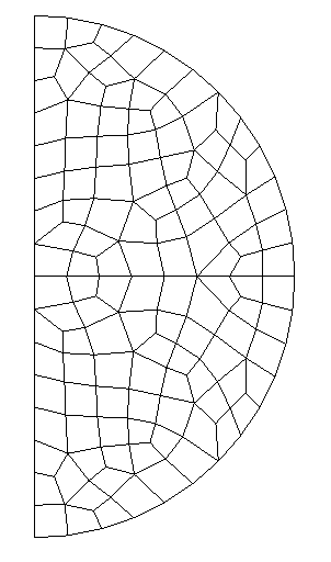 |
⇒ | 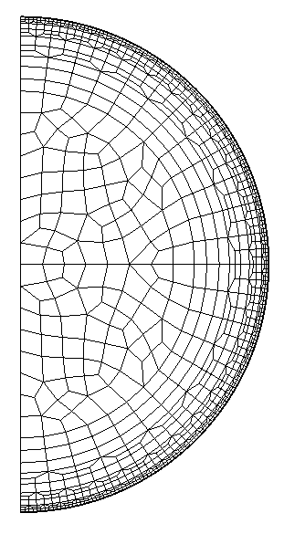 |
How to add circular layers to an initial mesh of a sphere
Similarly to the 2-D case, concentric spherical layers can be added by the code add_spherical_layer.cc (in the folder src/Program/Mesh, compiled with the target add_sphere) :
make add_sphere
The initial mesh must comprise only quadrilaterals on the boun- dary. The format of the file raff.don is the same as in the 2-D case. The final mesh is obtained by executing the following command :
./add_sphere.x quart_ball_hexa.mesh final.mesh 4 raff.don 0.7
The integer 4 is the reference of the external sphere (that will be extruded) in the mesh quart_ball_hexa.mesh. The last argument (here 0.7) is the radius of this external sphere. The code will produce a refined mesh named final.mesh here.
Basic tips for use of mesh generators (Gmsh, Modulef, Cubit, Harpoon, Geompack)
Gmsh
You can save mesh files in the native .msh format and use them in Montjoie. You can also generate files with .mesh format by using command geo2mesh :
geo2mesh cube.geo
The script geo2mesh is located on directory post and needs that convert2mesh is compiled (see above), you can place this script into a directory of your PATH variable. The mesh format does not handle curved elements, and therefore any high order mesh is converted into a first order mesh. You can specify the degree of curved boundaries in the second argument. For example, if you wish a second-order approximation, you have to type :
geo2mesh cube.geo 2
In that case, a .mesh file is not generated, and .msh file is kept. If you are using geo2mesh, you can ask to symmetrize the mesh by adding one of the following lines in the .geo file :
SymmetryX = 0;
SymmetryY = 0;
SymmetryZ = 0;
Modulef
In 2-D, you can use apno2mesh in order to interpret a data file of Modulef, call apnoxx (command of Modulef for generation of 2-D meshes) and convert the resulting mesh in .mesh format.
apno2mesh Carre
Cubit
A script cubit2mesh has been written, with the disadvantage to convert second-order curved mesh into a first-order mesh. You can also keep the .exo file, which is readable by Montjoie.
Harpoon
In Harpoon, you can import surface mesh with .stl format, by converting any other format to .stl fomrat :
convert_mesh sphere.mesh sphere.stl
The surface mesh must contain only triangles (no quadrilaterals). Then, Harpoon generates a volume mesh made of hexahedra, pyramids, wedges and tetrahedra, the surface mesh being remeshed with triangles and quadrilaterals. You have to export the output mesh in .neu format (Gambit Neutral File), which is readable by Montjoie (you can also convert this .neu file into a .mesh file if you wish). Another solution is tow write the output in .cas format (Nastran, Surface+Volume), but you will need to select an output in ASCII in the preferences of Harpoon.
Geompack
In 2-D, you can use geo2pack code in order to use Geompack with the .geo file. Nevertheless, this code is limited to basic .geo files (without loops and other transformations to define surfaces). You can generate all-quadrilateral meshes, hybrid meshes or triangular meshes. By default, it tries to generate an all-quadrilateral mesh.
geo2pack carre.geo
geo2pack carre.geo tri advance
geo2pack carre.geo hybrid poly
In 3-D, you can use geo3pack, which is similar to geo2pack. Again, the .geo file must be basic when defining surfaces and volumes. The generated mesh will be hexahedral dominant with pyramids, tetrahedra and wedges.
geo3pack cube.geo